


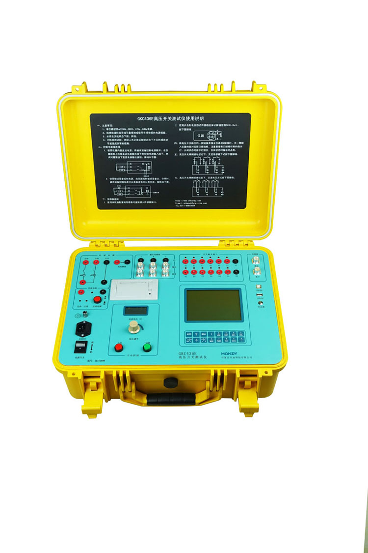
GKC436E Circuit Breaker Analyzer (with both sides grounded test)
INTRODUCTION
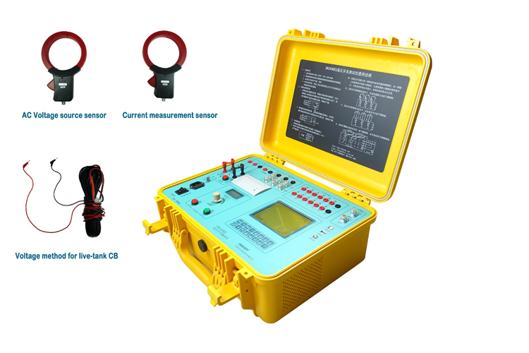
High voltage circuit breakers have traditionally been tested with at least one side of the contacts disconnected from ground. This has mainly been due to the challenges that arise when trying to test a circuit breaker with both sides grounded. Although this has been the accepted practice for many years, it has always put the test engineers or technicians at an increased safety risk. In order to perform circuit breaker timing under safer conditions, different methods of testing with both sides grounded have been developed using various technologies. HANDY GKC436E switchgear analyzer provide a new technologies method to test HV live-tank circuit breaker, dead-tank circuit breaker or gas-insulated switchgear (GIS). It makes your testing work safely, simplely.
FEATURES
1. GKC436E Circuit breaker test set is used for testing electrical and mechanical characteristic of all high voltage circuit breaker, earth switch and disconnect.
2. Measure the time parameters (close, open, asynchronous, bounce) of 12 main contacts. Measure the co-operate time between 6 main- and 6 auxiliary contacts.
3. Measure the pre-insert time and resistance of 6 resistor contacts
4. Measure the close and opening time at the state of circuit breaker both sides grounded.
5. Set with 12 contact state indicator lamps on panel. It is easy to judge close and open state.
6. There is one analog input channel and one digital input channel. Measure the travel, over-travel, rebound, overshoot and speed of the breaker by using resistance transducer or digital transducer.
7. Use digital rotary transducer for measuring angle.
8. Operate Close, Open, O-C-O, O-C, C-O control sequences.
9. Test the mechanical characteristic operated by CB manually.
10. Create and store 50 speed definitions of circuit breakers.
11. Built-in DC control output, can used for action voltage testing.
12. Built-in DC output for motor driving.
13. Measure the motor current curve while motor driving.
14. Use IGBT electrical switch for control outputs, with high precision and long life age.
15. Built-in DC/AC current sensor for measuring close and open control current.
16. Can store 60 test results in memory. Loss of power without loss of data.
17. The stored data can be transferred to USB disk.
18. Use the USB disk to update the tester software.
19. LCD displays the operation interface, test data, contacts, travel and current curves.
20. Thermal printer can print test result fast, include contacts, travel, and current curves.
21. Max 1000 times action testing automatically.
22. Use an USB cable connecting to Windows PC to operation.
23. Open and analyze data on PC, generate report and print A4 report.
24. Chinese and English interface selectable.
SPECIFICATIONS
| Contact inputs and Time Measurement |
|
Main contact channels: 12 Auxiliary contact channels: 6 Resistor contact channels: 6 |
|
Measurement time range: 0 to 20s Accuracy: ±0.05% rdg ± 0.1ms Resolution: 0.1ms |
| Sample rate: 10kHz to 100 kHz |
|
Resistive contact range: 50 to 2000Ω Accuracy: ±1% rdg ± 1 Ω Resolution: 1Ω |
| Motion Measurement |
|
Stroke measurement Accuracy: ±0.5% rdg ±0.2mm Resolution: 0.1mm Speed range: 0 to 20m/s Resolution: 0.01m/s |
|
Analog section: 1 channel Transducer input range: 0 to 5V Transducer resistance: 50Ω to 5kΩ |
|
Digital section: 1 channel Incremental transducer with RS422 Accuracy of angle: ±0.1° Resolution: 0.05° |
| Current Measurement |
| Coil current measurement: 0 to 30A (AC / DC) Resolution: 1mA |
| Motor current measurement: 0 to 40A (AC / DC) Resolution: 1mA |
| Control Section |
| Control output capacity: 300V/ 30A (AC / DC) |
| Built-in DC Power Source |
| DC power supply: 0 to 270V/ 20A, Power: 4kW |
| Voltage measurement: 0 to 300V Accuracy: ± 0.5% rdg ± 1V |
| General |
| Power supply: 198 to 264V AC 47 to 63Hz |
|
Environment:-20 to 50℃ Humidity ≤90%RH Non-condensing |
|
Weight:14kg Dimension:492 ×392 ×218mm |
-
Last article:GKC433F Switchgear Analyzer
-
Next article:GKC410D Switchgear Analyzer